Motion Control
The performance of a soccer robot is highly dependent on its motion ability. Together with the ability to walk, the kicking motion is one of the most important motions in a soccer game. However, at the current state the most common approaches of implementing the kick are based on a key frame technique. Such solutions are inflexible and take a lot of time to adjust the robots position correctly in order to use a key frame motion effectively. Moreover, they are hard to integrate into the general motion flow, e.g. to change between walk and kick the robot usually has to change to a special stand position.
Fixed motions such as keyframe nets perform well in deterministic environments, but they are restrictive. More flexible motions must be able to adapt to different conditions. Four possible specifications are adaptation to control demands, e.g. required changes of speed and direction to enable omnidirectional walk, adaptation to the environment, e.g. different floors with different heights and angles, kick execution according to ball state and fluent change between walk and kick.
At the current state we have a stable version of an omnidirectional walk control and a dynamic kick, both used in our gameplay. Along with further improvements of the dynamic walk and kick motions our current research focuses in particular on integration of the motions, e.g. a fluent change between walk and kick.
Adaptation to changing conditions requires feedback from sensors. We experiment with the different sensors of the NAO. Especially, adaptation to the visual data, e.g. the seen ball or optical flow, is investigated. Problems arise from sensor noise and delays within the feedback loop. As a correlated project we also investigate the paradigm of local control loops, e.g. we extended the Nao with additional sensors.
Walk
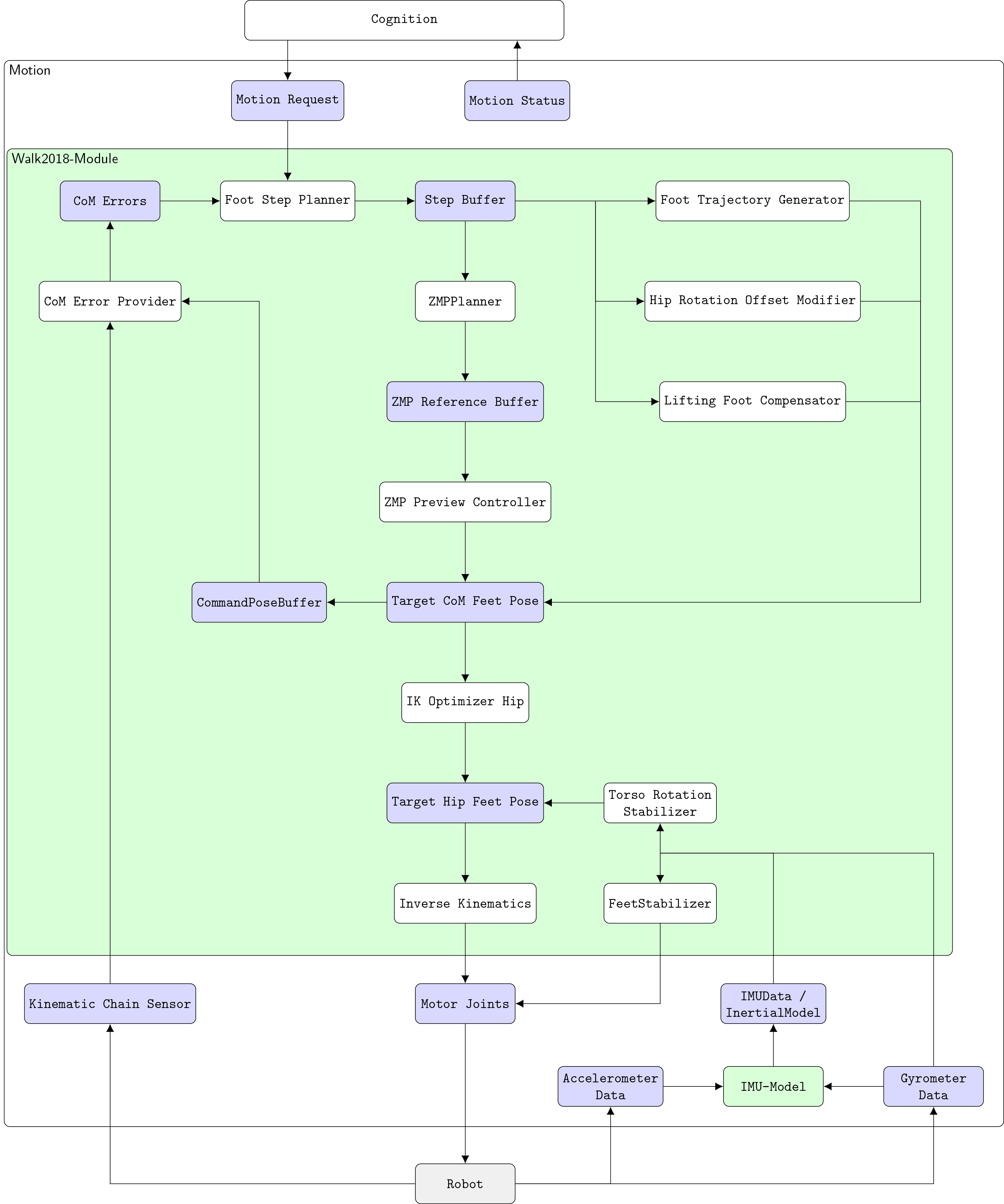
The algorithm we use to accomplish a walking motion can be subdivided into four components: the path planner, the step planner, the preview controller and stabilization.
The path planner is currently of very primitive nature, acting solely as a bridge for certain movement routines between behavior and motion control. The behavior part is presented in behavior chapter.
At first, the step planner determines the target position for the next step considering the walk request and various stability criteria. After that, a sequence of desired ZMPs (zero moment points) is planned for each execution cycle of that step. This sequence of ZMPs is used by the preview controller to compute the trajectory of the COM (center of mass) during the execution of the step assuming a linear inverted pendulum model. While the step is executed the foot's 3D trajectory is calculated on demand and combined with the corresponding COM pose to finally determine the target joint configuration using inverse kinematics.
Path Planner
The path planner is intended to calculate a collision free and optimal path from the robot towards a goal. Currently that intention is not fulfilled. Instead it is used as a bridge between the behavior and motion control. The behavior requests a certain routine, e.g. that the robot walks to the ball, and the path planner executes that routine by requesting steps from motion control. The types of routines that are implemented inside the path planner are walking or kicking routines.
Currently, there are two different interfaces to walk requests, i.e. standard and step control. A standard walk request consists of a target pose \((x, y, \theta)\), a frame of reference for the target pose in form of a local coordinate with its origin in the left foot, the right foot or the hip and a flag signaling fast, normal or slow step execution. Step control extends the standard interface by adding the following parameters: the target foot, the execution time in \(ms\), an angle \(d\) that impacts the final trajectory and \(s\in[0,\,1]\) which can scale the final trajectory resulting in faster execution. The flag in the standard interface maps itself to \(s\).
Step control allows for more fine-grained control over the actual steps, e.g. allowing retraction of the kicking foot after kick execution, and is thus preferred, but the standard interface is kept for backwards compatibility as not all possible movement routines related to walking are implemented inside the path planner. To allow this fine-grained control over actual steps the path planner implements a simple mechanism to ensure that a desired step is requested until actual execution of the step, unless the step becomes obsolete in the process.
Step Planner
The step planner calculates the next 2D positions of the feet based on the walk request inside the motion request.
The walk request and the current pose of the moving foot are transformed into the local coordinate system of the supporting foot. The supporting foot is the one that isn't executing the current step. The local coordinate system of the supporting foot is chosen for this as it is static whilst the step is being executed. This is not the case for the moving foot or the hip. The walk request is then applied to said current pose of the target foot resulting in the target pose for the step.
If the walk request was made using the standard interface the step planner is responsible for choosing the moving foot. Step control requests a specific foot explicitly.
The requested steps are restricted in regard of anatomic constraints as well as to increase the walks stability. A step is restricted elliptically in x-y-plane in general. The normal steps final dimensions are scaled by the cosine of the requested rotation. A big rotation therefore results in a small translation. In addition, the change in the step size is also restricted to increase stability. This prevents the robot to begin walking with the maximal possible step size. After applying these restrictions the step is finally added to the step buffer.
Independent of the requested steps the step planner might insert zero steps for increasing the stability of the walk. A zero step is a step in which no foot is moved.
Preview Control
The Preview Controller calculates the trajectory for the COM based on planed ZMPs. For estimating a stable trajectory for the COM we assume a linear inverted pendulum model with constant height. In each planning cycle of a step a target ZMP is added to the ZMP-buffer. The ZMP-buffer is used by the preview controller to calculate the target position, velocity and acceleration of the COM during a step. The following equation is used to determine the control vector [@Xu14Dissertation]:
Where \(x_k\) is a vector describing the location, velocity and acceleration of the COM at time \(k\). \(p_k\) is the ZMP and \(p_k^{ref}\) the target ZMP at time \(k\). \(K_x\), \(K_I\) and \(f_1, \cdots, f_N\) are the parameters of the preview controller and are pre-calculated. The next target COM \(x_{k+1}\) can be calculated using a linear motion model: $\(x_{k+1} = Ax_k + ub\)$
Stabilization
The simplified model can easily be affected by disturbances in the environment. Therefore a closed loop stabilization is required.
Different control techniques are used during step creation and execution to accomplish a stable walk.
During step creation the target step is adapted by a P-D-Controller mechanism to compensate small errors in the COM's position. Another mechanism uses the average COM-Error. If the average COM-Error exceeds a threshold an emergency stop is performed. This emergency stop is realized by zero-steps. As long as the COM-Error doesn't drop below a threshold the robot won't execute a step which is requested by a Walk-Request.
During the execution of a step three stabilization mechanisms are used. At first the height of the hip and its rotation around the x axis are adapted to compensate the moments appearing while a foot is lifted. A second stabilizer tries to keep the upper body in an upright position the whole time. And a third controller adapts the ankles according to the current orientation of the robot's body and its change in orientation.
Energy Efficient Stand
During games we have to deal with two problems regarding the hardware of the robots. The first problem is the increasing temperature of the joints, which affects the stability of walking. The second problem is the overall power consumption limiting the operational time. We observed that the robots are standing a lot on strategic positions during the game causing high energy consumption. The core of the problem seems to be that when going to the stand pose the joints are never reached completely and so remain in a state of permanent tension. In particular this can happen when the last step before stand was not completed exactly and the feet are a bit shifted. Therefore to address both problems we try to reduce the energy consumption and temperature increase during standing.
After the robot reached the target standing pose the measured joint positions are used as new target joint angles to ensure that each joint really reached the target position and thus relaxing the joints. Reducing the applied stiffness on the motors will result in a reduction of the applied current and so reduce temperature increase and the energy consumption. Additionally we try to use as less stiffness as possible while maintaining a posture close to the target standing pose. To achieve that the stiffness is linearly interpolated between 0.3 and 1 depending on the joint angle error for each joint.
The knee pitch and ankle pitch joints are the joints which have to carry most of the load. It was observed that in some cases the applied current can be reduced significantly if the target position of these joints is relaxed by the minimal step size of the motors. Therefore an offset is added to the joint positions. Every second the offset of the joint with the highest current consumption is relaxed, i.e., increased (for knees) or decreased (for ankles), by the minimal step size of the motors.
Both energy saving approaches may result in a drifting of center of mass. So if the difference to the target center of mass becomes too large regarding translation and rotation the offset are reset and the standing posture is corrected again with full stiffness.